In this guide
Ask around and almost every installer has a CT clamp story — a system that wouldn’t report correctly, a battery that refused to charge, an inverter throwing Error 401 on a job that should’ve been straightforward. Nearly all of it traces back to two things: which way the clamp is facing, and whether the inverter is actually receiving data from it. Get those right and most of the rest sorts itself out.
The One Rule That Matters Most
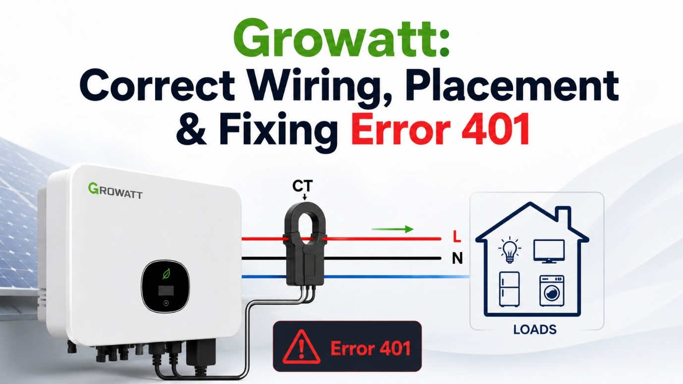
Every CT clamp is directional. It’s marked with an arrow, or sometimes P1/P2 or K/L labels, indicating which way it’s designed to measure current flow. This is genuinely the single most common installation error across the industry — not specific to any one brand — and it produces the exact same symptom every time: import and export readings invert. The system reports you’re exporting when you’re actually importing, a battery that should be charging from excess solar won’t, and everything downstream of that reading — export limiting, VPP dispatch, self-consumption logic — gets confused.
Single Phase Wiring
On a single-phase supply, one CT clamp on the incoming active conductor is enough to measure the whole property’s import/export. It’s typically fitted on the main incomer — after the meter, before it splits off to the switchboard — with the signal cable run separately to the inverter’s meter/CT input, not through the switchboard itself.
Three Phase Wiring
Three phase needs a CT on each of the three active conductors — L1, L2 and L3 — all facing the same direction, or more commonly on larger systems, a dedicated 3-phase meter (like an SDM630-series meter) that reads all three phases itself and reports back to the inverter over RS485 rather than through three separate CT signal wires. Either way, the direction principle doesn’t change per phase — get one backwards and that phase’s readings invert while the other two stay correct, which is a genuinely confusing fault to diagnose if you don’t know to check each phase individually.
Common Mistakes
CT clamped on the load-side cable (after the switchboard splits to circuits) rather than the single main incomer — it only sees part of the property’s load, not the whole picture.
CT clamped on the single main incoming active conductor, before it splits to any circuits — sees the property’s total import/export in one reading.
Arrow facing the switchboard/load side. Every reading inverts — the portal shows exporting when the house is actually drawing from the grid.
Arrow facing back toward the grid/meter side, matching the direction power actually flows in from the street.
Signal cable plugged into the DRM port instead of the SYS COM (or equivalent meter/CT) port — physically similar connectors, completely different function.
Signal cable in the correct, manufacturer-labelled meter/CT communication port — check the port label against the manual, not just “the RJ45 that looks free.”
Extending a CT signal cable with insulation-piercing clips, twist-and-tape joins, or whatever’s on the van — these corrode and loosen over time, causing intermittent readings or Error 401 that comes and goes rather than staying put.
Extended with a proper terminal block or soldered, heat-shrunk join, matching the original cable’s gauge and (for RS485 meters) keeping the pair twisted — a join should be as reliable as the cable either side of it.
Want our full brand-specific wiring references?
We keep configuration guides on file for the brands we install most — happy to share the relevant one for your job.
Get in touchFixing Error 401
Error 401 is specific to Growatt hybrid and battery inverters, and it means one thing: the inverter isn’t getting data from the meter or CT. It’s not one fault — several different underlying problems all trigger the same code, which is exactly why it trips people up. In Australia, a meter or CT is mandatory on a battery system, since the inverter needs it to manage export limits and charge/discharge cycles correctly — so this isn’t a code you can just dismiss or disable your way past.
Work Through These in Order
Quick Reference: Symptom to Likely Cause
| Symptom | Likely cause |
|---|---|
| 401 appears immediately after battery install, previously fine | Power sensor/meter function not yet enabled for the new battery configuration |
| Readings present but obviously wrong (import shown as export) | CT clamp installed backwards — check the arrow, not the wiring |
| No data at all, voltage test shows nothing | Wrong port (DRM instead of SYS COM), or a damaged cable/connector |
| Voltage present but still no communication | Meter address or baud rate mismatch |
| Everything checks out, still no data | Faulty meter — contact Growatt Australia support |
Real Case Study: Diagnosing Reversed Phases
Everything above is the general principle. This is what that troubleshooting actually looked like on a real job — a genuine reversed-phase fault on a three-phase install, worked through from first symptom to final fix.
The Job
A three-phase installation using a CHINT DTSU666 smart meter for AC-coupling monitoring. Like a fair few larger properties, this one had the meter box sitting well away from the shed where the battery and inverter actually lived — not next to each other the way a straightforward suburban install usually is. That distance didn’t cause this particular fault, but it’s exactly the kind of layout the acreage section below covers.
The system was installed and commissioned, and the inverter kept throwing Error 401 — CT1 flashing red on the meter itself.
The First Check
The natural first move with any CT-related fault is checking the arrow direction — and that’s exactly where the diagnosis started. Growatt’s support team, seeing the recurring 401 warning, raised the possibility that the incoming supply looked reversed at the meter.
That first check came back clean: the CT arrow was pointing the correct way. Which meant the fault had to be something other than the simple, most common reversed-CT scenario covered above — the arrow was right, but something else underneath it wasn’t.
The next piece of guidance was more specific: on a three-phase board, the incoming supply’s colour convention needs to land on the correct phase terminals — red on L1, white on L2, blue on L3. Worth flagging early, but on this job it turned out not to be where the actual problem was either.
Isolating and Testing
With the simple checks not explaining the fault, the next step was isolating the system entirely — inverter and batteries both off — and pulling the meter’s live per-phase current readings (IA, IB, IC) to see what it was actually reporting.
All three initially showed 0W, which meant checking further upstream: confirming exactly which MCB was feeding the inverter, then independently measuring current on each incoming phase — red, white and blue — with a clamp meter, and comparing those readings directly against what the meter itself displayed for IA, IB and IC.
The clamp meter told a clear story: the white and blue phases were reading unusually high current — 3.2A and 9A respectively — against just 1.1A on red. Currents that uneven, on a system that should have been drawing evenly, meant something was measuring incorrectly rather than the load itself genuinely being that unbalanced.
The Diagnostic Signal
With the currents confirmed inconsistent, the next step was pulling the meter’s live active power log — and this is where the fault became unambiguous:
| L1 (W) | L2 (W) | L3 (W) |
|---|---|---|
| 216.9 | -774.4 | -986.1 |
| 220.7 | -781.6 | -65.1 |
| 216.6 | -775.6 | -992.0 |
With solar and batteries both switched off, the property should have been purely importing — meaning every phase should read positive active power, full stop. L1 did exactly that. L2 and L3 both read negative, which is only possible if those two CTs were measuring the flow backwards.
Finding the Root Cause
Confirming that two phases were reversed was the easy part. Finding why took one more step: checking the CT connector plug itself for a mismatch, and comparing it against the meter’s actual terminal sequence.


A Partial Fix
Worth including honestly rather than editing out: the first correction attempt fixed part of the problem, not all of it. Only one of the two reversed CTs was re-terminated in the initial pass — a genuinely common pattern, since once one obviously-reversed phase is found and corrected, it’s easy to assume the job is done rather than re-checking every phase against the meter’s readings again from scratch.

A follow-up photo of the open board, checked again, confirmed it: still not right. The fix needed a second pass.
Want this checked before it becomes a callback?
Our team verifies CT phase assignment against the meter’s own readings on every three-phase commissioning — not just the arrow direction.
Get in touchFully Resolved
With every phase re-checked against the meter’s terminal sequence rather than just the one that had originally triggered the alarm, the second correction held. The inverter and batteries were switched back on, and the meter’s readings settled into what they should have looked like from the start — all three phases positive, no more Error 401.
The Technique, Distilled
Stripped down to a repeatable sequence, this is the diagnostic process for any reversed-phase suspicion on a three-phase CT/meter setup:
Where to Physically Put It
The CT or meter needs to sit somewhere it can be wired to the main incomer, has room for the signal cable run back to the inverter, and stays accessible for future fault-finding. That’s not always inside an already-crowded switchboard.
No Room in the Switchboard?
An IP-rated outdoor enclosure is a completely standard solution, not a workaround — this is a real, commercially available product category built specifically for outdoor metering and electrical equipment, including Australian-made options.
Choosing the enclosure
- IP65 or IP66 for a location fully exposed to weather
- A lower rating like IP23 can suit a sheltered spot (under an eave, inside an already-covered meter box area) but isn’t right for open exposure
- Coastal or high-humidity sites — check for a marine-grade or higher-IP option specifically
Getting it right
- Cable entries properly glanded and sealed — an unsealed entry defeats the IP rating regardless of the box itself
- Mounted with clear access for future servicing, not wedged somewhere it’ll need removal to reach
- Kept out of direct water pooling or splash-back zones even within its rated tolerance
For the CT itself specifically, remember it just needs to clamp around the main active conductor — it doesn’t need to live inside the switchboard at all, as long as there’s a safe, accessible point on that conductor to fit it and a clear cable run back to the inverter.
SPH-HUB Configuration Reference
Everything above is the general principle. In practice, which port you use and which meter you select on-screen depends on exactly what’s being monitored — a straightforward grid connection, or an existing second inverter being AC-coupled in. Growatt’s SPH-HUB covers six common scenarios. Here’s each one, at a glance.
The Six Cases at a Glance
| Case | Phase | Meter / CT | Port(s) | Screen selection |
|---|---|---|---|---|
| 1 | Single | Inbuilt meter, provided CT | Inbuilt Meter1 | InMeter1 |
| 2 | Single | SDM120CT (not using inbuilt) | Meter1/CT1 | Meter1 |
| 3 | Single | Inbuilt meter + SDM120CT | Inbuilt Meter1 + 485-2 | InMeter1, then Meter2 |
| 4 | Single | Two SDM120CT | Meter1/CT1 + 485-2 | Meter1, then Meter2 |
| 5 | Three | SDM630MCT (not using inbuilt) | Meter1/CT1 | Meter1 |
| 6 | Three | CHINT 666 (2 CTs on one meter) | Meter1/CT1 | CHINT6CT |
Cases 1 & 2: Grid Monitoring Only
The straightforward setup — no existing second inverter to worry about, just the SPH-HUB reading grid import/export. Case 1 uses the CT that comes provided with the unit, wired into the Inbuilt Meter1 port. Case 2 swaps that out for an external SDM120CT wired into Meter1/CT1 instead — functionally the same job, different hardware. Both use the single-phase wiring principle covered above: one CT (or the meter’s internal sensing) on the main incomer, direction pointing back toward the grid, referred to in Growatt’s own documentation as “Point to Load.”
Cases 3, 4 & 6: AC-Coupling an Existing Inverter
These three cases share the same underlying concept: when there’s already a separate, existing solar inverter on-site that the SPH-HUB needs to work alongside, you need two monitoring points, not one — one reading the grid connection, a second specifically watching what the existing inverter is doing. That second reading is what lets the SPH-HUB decide when to charge the battery from the existing inverter’s excess output.
The only difference between Cases 3, 4 and 6 is which hardware does each job:
- Case 3 — inbuilt meter (provided CT) for the grid side, a separate SDM120CT for the existing inverter
- Case 4 — two separate SDM120CT units, one for each side
- Case 6 — a single CHINT 666 three-phase meter handling both jobs at once, using its two CT inputs (commonly colour-coded — black for the grid side, green for the existing inverter)
Case 5: Three Phase, Not Using Inbuilt Meter
Where a three-phase system isn’t using the inbuilt meter at all, an SDM630-series meter reads all three phases through its own three CT inputs and reports back to the SPH-HUB over a single communication cable into Meter1/CT1 — this is the three-phase wiring approach already covered earlier in this guide, just naming the specific meter model Growatt’s own documentation references.
Finding the Switch on Acreage Properties
This catches out more site visits than it should. On a suburban block, the switchboard is next to the meter box on the house, full stop. On acreage, that’s often not true at all.
Check here first
On larger rural and acreage lots, network rules generally require metering equipment to be positioned somewhere vehicle-accessible — which in practice usually means the front property boundary or a private power pole near the driveway entrance, not the house itself. This is standard, documented practice, not a one-off oddity.
What that means for a battery install: there’s very likely a meter and a main switch/service fuse out at the boundary, then a submain cable running from there to a separate switchboard at the house — and that house switchboard is what actually has the circuit breakers you’d expect to see. Both matter for a battery install:
- The boundary metering point is where the retailer’s meter and the main service fuse live — this is what a Level 2 ASP would need to access for anything involving the actual point of supply
- The house sub-board is where your CT clamp, inverter connection and everyday circuits actually are — this is almost always where the battery installation work itself happens
A Real Example
This is genuinely how far apart the two points can sit on a larger property. On one recent job, the battery was installed in a pool house, while the main switch and metering point sat in a shed roughly 30 metres away — close enough to be “on the same property,” far enough that assuming they’d be side by side would have wasted a site visit.


Worth noting what the switchboard photo gets right: a clearly hand-labelled “MAIN Switch,” legible zone numbering for everything else on the board, and both required warning labels in place — arc flash hazard, and multiple battery systems requiring all isolators off before work. That level of labelling is exactly what turns “which one is the main switch” from a guessing game into a five-second glance.
This same layout pattern — meter box well away from where the battery actually sits — shows up again in the real case study above, on a different job entirely.
Frequently Asked Questions
- Which way should a CT clamp arrow point?
- The arrow (or the side marked K/L or P1) should point back toward the grid — away from the loads it’s measuring. This is consistent across almost every manufacturer’s guidance. If it’s installed backwards, import and export readings invert: the system reads exports as imports and vice versa, and battery charge/discharge logic gets confused.
- What causes Error 401 on Growatt inverters?
- Error 401 means the inverter isn’t receiving data from the meter or CT. The most common causes are incorrect wiring between the meter and the SYS COM port, a damaged plug or connector, an incorrect meter address or baud rate, or the power sensor/meter function not being enabled in the inverter’s settings when a battery is fitted. Less commonly, the meter itself is faulty.
- Can a CT or meter enclosure be installed outdoors if there’s no room inside?
- Yes. IP-rated enclosures built specifically for outdoor electrical and metering equipment are a standard, commercially available product — commonly IP65 or IP66 for fully weather-exposed locations. The enclosure needs to be rated appropriately for its exposure, mounted correctly, and any cable entries properly sealed. This is a normal solution, not a workaround.
- Where is the main switchboard on an acreage property?
- On larger rural and acreage blocks, the metering equipment and main switch are very often located at the property boundary or on a private power pole near the driveway entrance, not at the house itself — network rules for larger properties generally require the metering position to be vehicle-accessible. A separate sub-board near the house holds the everyday circuit breakers. If you can’t find a switchboard at the house, check the front boundary and any private pole first.
- Does a CT clamp go on the active wire or the neutral?
- The active (live) conductor is the standard, manufacturer-recommended position. Some CTs can technically work on the neutral with the arrow reversed, but this isn’t the conventional setup and isn’t recommended unless a manufacturer’s documentation specifically allows it for your model.
- How do you tell if CT phases are reversed without special equipment?
- With solar and batteries switched off, every phase should read positive active power on the meter, since the house is purely importing at that point. A phase reading negative active power under those conditions is reversed. This works with just the meter’s own display, no extra equipment needed.
- Why would a clamp meter reading not match the smart meter’s own reading?
- If a CT clamp is on the wrong phase conductor, or its colour-coded label doesn’t correspond to the terminal it’s wired into, the smart meter’s IA/IB/IC readings won’t line up with what you measure directly on each incoming phase with your own clamp meter. Comparing the two is a reliable way to catch a mismatch.
- Does a CT clamp’s colour label always match the wire colour it goes on?
- Not necessarily — this is a common assumption that causes exactly this kind of fault. A CT clamp’s colour label corresponds to its position in the meter’s terminal sequence, not necessarily the colour of the conductor it’s clamped around. Always confirm against the meter’s own labelling and manual, not by matching colours intuitively.
- Why did the first correction attempt still show as wrong?
- Only some of the reversed CTs were corrected on the first attempt — the underlying phase mismatch wasn’t fully resolved until every CT was checked against the meter’s actual terminal sequence, not just the one that seemed most obviously wrong. It’s a reminder to re-verify all phases after a correction, not just the one that triggered the original alarm.